Diesel Cycle Definition
The Diesel cycle is a thermodynamic cycle that best represents the working of a diesel internal combustion engine.
Before we understand how it does this, let's briefly look at the working of a CI engine - this will help you in relating to the processes of the Diesel cycle that we will be explaining in subsequent sections.
How do Diesel engines work?
This animation of a CI engine piston shows how the linear motion of the prison is converted into rotation, which rotates the driveshaft to produce the power output. The 4 "strokes" of the cycle are also shown, and will be explained later. Wikimedia Commons CC-BY-SA-3.0There are three important parts that we need to know for us to understand the basic principle of how a CI engine works: The piston, the crankshaft, and the combustion chamber. The piston slides up and down, inside the combustion chamber. This chamber is sealed and airtight, and changes in
volume as the piston slides up and down. The other end of the piston is connected to the crankshaft. Clever engineering converts the linear motion of the piston into rotation of the crankshaft that provides the power output of the engine.
The most important difference between a gasoline engine and a diesel engine is in the ignition of the fuel. Diesel engines have a high compression ratio. This compresses the air-fuel mixture to very high pressure, usually assisted by a turbocharger. At this stage, the temperature of the fuel reaches a point where it can ignite without any spark plugs.
Now let's see how the chemical energy in the Diesel fuel is converted into mechanical energy. The internal combustion engine takes four steps to achieve this. Each step is called a stroke as it represents a single upwards or downwards motion of the piston.
Diesel cycle Process
The diesel cycle has four processes. These can each be observed in the animation above, and in the PV diagram in the next section.
Process 1 [suction stroke] - This is when the piston first moves downward, creating a vacuum that sucks air into the combustion chamber.
Process 2 [compression stroke] - Once the piston reaches the lowest point it moves up again and compresses the air in the combustion chamber to very high pressure. The pressure is so high that it heats up the air to beyond the temperature at which diesel ignites.
Process 3 [power stroke] - The power stroke starts with a bang, as at the end of the compression cycle (process 2) the fuel is injected into the combustion chamber via the fuel injector. The fuel ignites as it mixes with the high-temperature air inside the chamber. This controlled explosion forces the piston back downwards producing work.
Process 4 [exhaust stroke] - Finally, this is when the piston moves back up and pushes the by-products of combustion (mainly \(\mathrm{CO_2}\) and heat) out of the combustion chamber. This is called the exhaust stroke. After this, the piston repeats process 1 and follows the same cycle once again.
Diesel Cycle Diagram
Now let's explain the above paragraph in terms of thermodynamics. Here we have a PV (pressure-volume) diagram that depicts an ideal Diesel cycle. The processes mentioned above can be identified in the figure below.
PV Diagrams
PV Diagrams (click on the link for an in-depth understanding of PV diagrams) are used to graphically represent various different thermodynamic cycles. The pressure is measured on the y-axis and the volume is measured on the x-axis. This makes it a convenient way to represent the change in volume and pressure, which is usually important when we're looking at thermodynamic cycles.
Here are a few important properties of the PV diagram:
- The y-axis represents the pressure, and the x-axis represents the volume.
- Increasing pressure values follow a down-to-up direction, and increasing volume values follow left to right.
- An arrow indicates the direction of the processes.
Some thermodynamic terms that are used to describe processes in PV diagrams are defined below:
An isobaric process is a thermodynamic process where pressure remains constant.
~
An adiabatic process is a thermodynamic process where there is no transfer of heat or mass to the surroundings.
~
An isentropic process is a thermodynamic process that is both adiabatic and reversible.
~
The ignition point is a temperature and pressure combination at which a fuel spontaneously ignites.
Diesel Cycle PV Diagram
Below we have a PV diagram that depicts a theoretically ideal Diesel cycle. The processes mentioned above can be identified in the figure below.
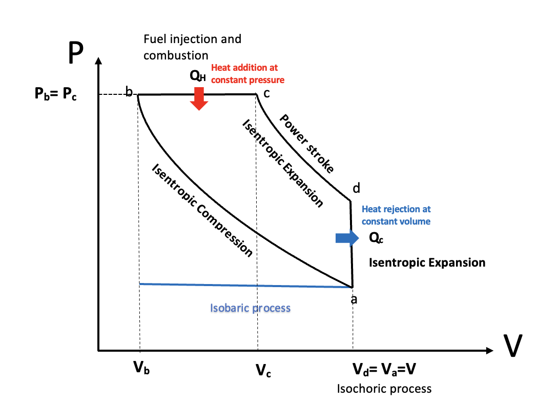
PV Diagram of a Diesel cycle, StudySmarter Originals
Now that you have an understanding of how a diesel engine operates, we will explain the working of the diesel engine using the diesel cycle.
Suction stroke
The horizontal blue line represents the suction stroke (intake stroke) - starting on the left of the blue line at at volume, the volume of the chamber increases because the piston moves downward, drawing air into the combustion chamber. This process is isobaric as the pressure remains constant.
Compression stroke
Isentropic compression from a to b - this is the compression stroke we mentioned in the above section. The air gets compressed by the piston as it moves up and the combustion chamber volume decreases, increasing the pressure rapidly. However, there is no exchange of heat. This makes it an adiabatic process. The combustion chamber only contains air at this stage. Due to the increase in pressure, the air is heated beyond the ignition point of diesel.
Power stroke
Heat addition at constant pressure, b to c
This process covers the first part of the power stroke. Right before the beginning of the power stroke, the fuel injectors inject droplets of fuel into the combustion chamber. The contact between the diesel and heated air auto ignites the mixture, with the controlled explosion driving the power stroke. The combustion of the fuel is completed at point c. The heat being added to the system is represented by \(Q_H\) . This process lasts for a very short amount of time. As the piston moves downwards to increase the combustion chamber volume during the power stroke, the heat added to the engine happens at a constant pressure. This makes it an isobaric process.
Due to the heat addition happening at constant pressure, the diesel cycle is also known as the constant pressure cycle.
Isentropic expansion, c to d
This is the final part of the power stroke. The high pressure after the explosion continues to push down the piston, increasing the combustion chamber volume. Here the thermal energy from the combustion is converted into mechanical work. This process is also an adiabatic process.
Heat rejection at constant volume, d to a
This is where the heat is expelled from the combustion chamber as the piston reaches the bottom of the power stroke. The volume remains constant hence it is an isochoric process. The heat that is expelled is represented by \(Q_C\). At this stage, the pressure also reduces significantly. This is very similar to the final process of the Otto cycle.
Exhaust stroke
The blue line in the opposite direction to the suction stroke represents the final exhaust stroke where the gases are expelled as the piston moves back upwards, ready to begin the cycle again.
Diesel Cycle Efficiency
The formula for the efficiency \(\eta\) of the Diesel cycle is given by the following equation.
A heat engine's thermal efficiency is defined as the ratio of useful work done \(W\), to the heat input at high temperature, \(Q_H\).
$$\mathrm\eta=\frac{W}{Q_H}=\frac{{\mathrm Q}_{\mathrm H}+{\mathrm Q}_{\mathrm C}}{{\mathrm Q}_{\mathrm H}}=1+\frac{{\mathrm Q}_{\mathrm C}\;\cancel{(\mathrm{Joules})}}{{\mathrm Q}_{\mathrm H}\;\cancel{(\mathrm{Joules})}}$$
In order to see how the thermal efficiency of an idealized diesel cycle changes when varying properties of the engine, there are two key ratios we can define; the cut-off ratio and compression ratio.
Compression Ratio
The compression ratio \(R_c\) is the ratio of the volume of the combustion chamber when the piston is at the bottom to the volume when it is at the top, measured during the compression stroke.
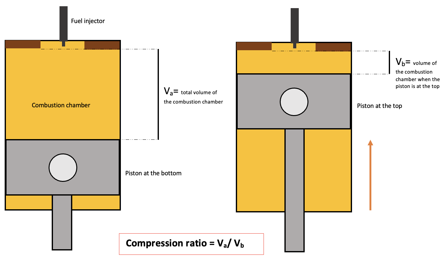
Compression ratio in a diesel engine, StudySmarter Originals
It helps us understand how much the air is compressed inside the engine before the power stroke. Commonly, diesel engines have a compression ratio from 16:1 to 20:1. This is very high compared to the Otto cycle. It is given by the following equation,
$$R_c=\frac{V_a}{V_b}$$
Fuel Cut-Off Ratio
The fuel cut-off ratio \(R_v\) is the volume after combustion \(V_c\) to the volume before combustion, \(V_b\).
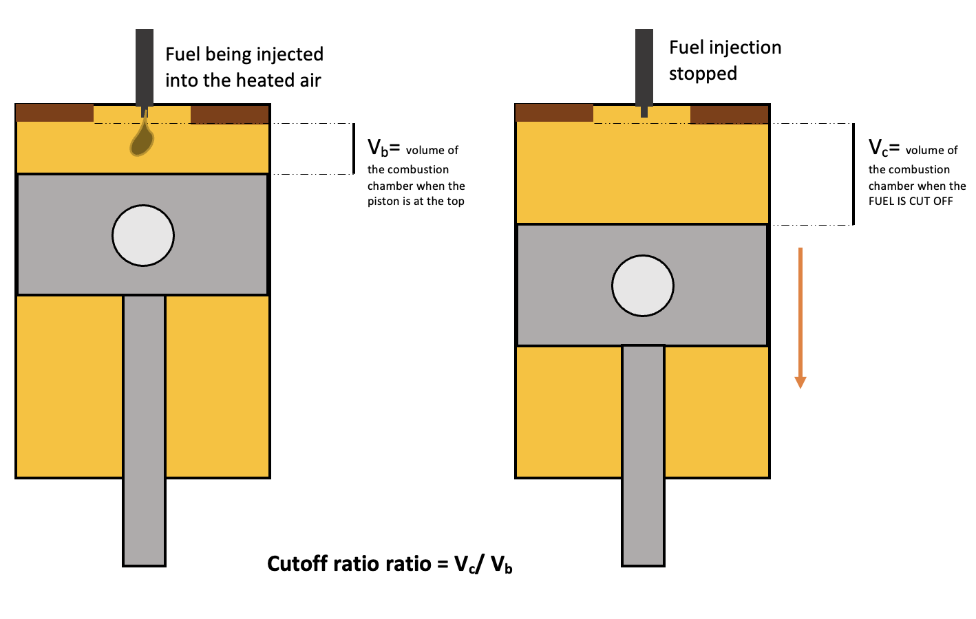
Cut off ratio of a diesel cycle, StudySmarter Originals
$$R_v=\frac{V_c}{V_b}$$
The volume \(V_c\) is the volume at which the fuel injection is cut off, hence the name. Remember fuel is supplied by the injector to the hot air. This ratio can help us understand how much the chamber expands during the combustion process.
By applying the conditions of the idealized diesel cycle, we can rewrite these ratios in various ways:
We know that the volumes at points a and d (heat rejection at constant volume) are equal, as it is an isochoric process.
$$V_a=V_d$$
This means that the compression ratio can also be written as:
$$R_c=\frac{V_a}{V_b}=\frac{V_d}{V_b}$$
And we can also rewrite the expansion ratio as:
$$R_e=\frac{V_d}{V_c}=\frac{V_a}{V_c}$$
Diesel Cycle Formula and Equation
 Equations used in the diesel cycle, StudySmarter Originals
What if we wanted to define the efficiency of the diesel cycle using its temperature? We can calculate the heat added and released to the system by using the specific heat of air and temperatures at each point in the cycle.
$$Q=mC\triangle T$$
$$\mathrm{Heat}=\mathrm{mass}\;\times\;\mathrm{specific}\;\mathrm{heat}\;\times\;\mathrm{change}\;\mathrm{in}\;\mathrm{temp}$$
Apply this equation for both processes where heat is added and released. Since the heat is added at a constant pressure between b to c, we use \(C_p\), which is the specific heat of air at constant pressure.
$$Q_H=mC_p(T_c-T_b)$$
Heat rejection happens at constant volume from d to a, hence we use \(C_v\), which is the specific heat of air at constant volume.
$$Q_C=mC_v(T_d-T_a)$$
Substitute these expressions into our earlier equation for thermal efficiency, and we obtain:
$$\eta=1-\frac{Q_C}{Q_H}=1-\frac{\cancel{m}C_v(T_d-T_a)}{\cancel{m}C_p(T_c-T_b)}$$
To make the equation simpler, we can say that gamma \(\gamma\) is the ratio of the specific heats of air at constant pressure \(C_p\) and constant volume \(C_v\):
$$\gamma=\frac{C_p}{C_v}$$
Simplifying the above equation for efficiency, we get:
$$\eta=1-\frac{1}{\gamma}\frac{T_a-T_d}{T_c-T_b}$$
We now have the thermal efficiency in terms of temperature, but the ratios we defined earlier are in terms of volume! How can we express the efficiency formula in terms of volumes? First, we need to further rearrange the equation:
$$\eta=1-\frac{1}{\gamma}\frac{T_a}{T_b}\frac{\frac{T_d}{T_a}-1}{\frac{T_c}{T_b}-1}$$
By applying the thermodynamic process conditions to these temperature ratios, we can write them as the volume ratios we defined earlier. As the compression stroke from a to b is isentropic, the temperatures and volumes have the following relation:
$$\frac{T_b}{T_a}=\left(\frac{V_a}{V_b}\right)^{\gamma-1}={R_c}^{\gamma-1}$$
Similarly, the isentropic expansion from c to d in the power stroke means that:
$$\frac{T_c}{T_d}=\left(\frac{V_d}{V_c}\right)^{\gamma-1}=\left(\frac{V_b}{V_b} \frac{V_d}{V_c}\right)^{\gamma-1}=\left(\frac{V_d}{V_b} \frac{V_b}{V_c}\right)^{\gamma-1}$$
$$\frac{T_c}{T_d}=\left(\frac{R_c}{R_v}\right)^{\gamma-1} $$
And finally, we need to rewrite the expression for the cut-off ratio in terms of temperatures. By applying the ideal gas equation \(PV=nRT\) and seeing that the pressures at points b & c are the same, we can write the ratio as:
$$R_v=\frac{V_c}{V_b}=\left(\frac{\cancel RT_c}{\cancel{P_c}}\right)\left(\frac{\cancel{P_b}}{\cancel RT_b}\right)=\frac{T_c}{T_b}$$
Having defined these temperature ratios in terms of the compression and cut-off ratios, we now use algebra to simplify the efficiency equation to these parameters.
$$\eta=1-\frac1\gamma\frac{T_a}{T_b}\frac{\frac{T_d}{T_a}-1}{\frac{T_c}{T_b}-1}=1-\frac1\gamma\left(\frac1{R_c^{\gamma-1}}\right)\left(\frac{\frac{T_d}{T_c}\frac{T_c}{T_b}\frac{T_b}{T_a}-1}{R_v-1}\right)$$
$$\eta=1-\frac1\gamma\left(\frac1{R_c^{\gamma-1}}\right)\left(\frac{\left({\displaystyle\frac{R_v}{R_c}}\right)^{\gamma-1}R_vR_c^{\gamma-1}-1}{R_v-1}\right)$$
This simplifies to a final efficiency equation of:
$$\eta=1-\frac1{R_c^{\gamma-1}}\left(\frac{R_v^\gamma-1}{\gamma(R_v-1)}\right)$$
The value \(\gamma\) mostly remains constant for automobile engines on the earth as the ratio of specific heat for air is about 1.4. As you can see, the above equation for the efficiency of the diesel cycle shows the relationship between the thermal efficiency of the diesel cycle and the compression and cut-off ratios. When the cut-off ratio increases the thermal efficiency of the diesel will decrease. When the compression ratio increases, the thermal efficiency will increase.
 The graph above uses the equation we just derived to show how the diesel cycle efficiency changes with varying compression ratios at different cut-off ratio values. StudySmarter Originals.
This brings us to the end of this article. Let's look at what we've learned so far.
Diesel Cycle - Key takeaways
- The Diesel cycle is a thermodynamic cycle that best represents the working of a diesel engine.
- A diesel cycle undergoes the following four processes:
- Intake stroke
- Compression stroke
- Power stroke
- Exhaust stroke
- The formula for the efficiency of the Diesel cycle is given by the following equation.
- The compression ratio \(R_c\) is the ratio of the volume of the cylinder when the piston is at the bottom to the volume of the cylinder when it is at the top, measured during the compression stroke.
The fuel cut-off ratio \(R_v\) is the volume after combustion to the volume before combustion.
The equation for the efficiency of a diesel cycle in terms of the compression and the cut-off ratio is given by:
When the cut-off ratio increases the thermal efficiency of the diesel will decrease.
When the compression ratio increases the thermal efficiency will increase.
Similar topics in Physics
Related topics to Further Mechanics and Thermal Physics


